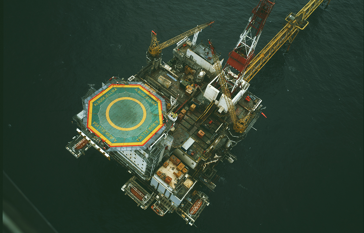
Albuskjell 1/6 A
The Albuskjell oil and gas/condensate field lay 21 kilometres north-west of the Ekofisk Complex and extended across blocks 1/6 and 2/4, licensed to Norske Shell and the Phillips group respectively. It was later unitised on a 50-50 basis.
Shell drilled discovery well 1/6-1X in 1972, in cooperation with Phillips, close to the boundary with block 2/4. The Albuskjell structure formed rather differently from other fields in the Greater Ekofisk area. Deposited 22-55 million years ago over a salt dome, its producing layer comprises carbonate rocks with some thin strips of shale.
Albuskjell 1/6 A produced from 11 wells and was tied back by gas and oil pipelines via Albuskjell 2/4 F to Ekofisk 2/4 R. A separate flare stack was linked to the platform by a bridge.
Processing comprised an oil/gas separator. Gas was dehydrated and compressed before export in a 24-inch pipeline. The separated oil was exported through an 18-inch line. Before being piped away, the oil and gas passed through a fiscal metering station to measure the volumes produced.
The platform was designed in a collaboration between Cork Shipyard, Oil Industry Services (OIS), Nylands Verksted, Tangen Verft, Aker Stord and Thyssen. Morco AS was the drilling contractor.
Like that on Albuskjell 2/4 F, the jacket (support structure) for 1/6 A was unusual because its two topmost frames were filled with water to prevent them heating up in the event of a fire. It was built at Aker Verdal, with the module support frame (MSF) fabricated by Aker Stord.
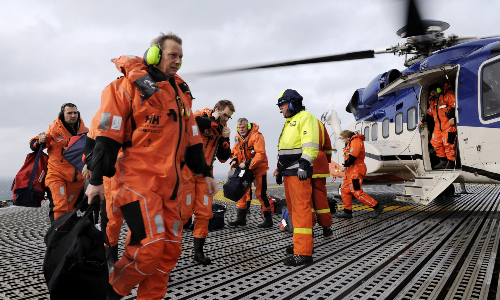
The living accommodation provided 46 beds, later 96.
The water depth was 70 metres.
Total weight of platform and pipelines was 25 300 tonnes.
The tip of the flare stack was 94 metres above sea level.
The derrick was 74 metres tall.
It was originally designed as a combined production, drilling and accommodation platform, but the derrick and drilling equipment were removed as early as 1979. The accommodation module with helideck was replaced in 1983 to increase beds from 46 to 96. The actual lifting operation was performed by the Balder crane barge from Heerema/Seaway.
When the Albuskjell field was shut in during July 1998, it had produced
46 million barrels or 7.353865 million standard cubic metres (scm) of oil
15.53439 billion scm of gas
990 139 tonnes of natural gas liquids (NGL)
Wellheads
Once a well has been fully drilled, it is completed for either production or injection. The purpose of well completion is to isolate the oil/gas production flow (wellstream) so that the whole path from reservoir to platform topside is leak-free.
This is achieved by running production tubing inside the casing (well liner) installed during drilling. These tubes are attached to the wellhead on the platform, which seals the top of the casing and provides a system for controlling pressure in the well.
Reservoir pressure causes crude oil/gas to flow up through the production tubing to the wellhead, which contains master and choke valves. These make it possible to shut down a producer or to adjust the desired volume of flow from each producer.
The Xmas tree (so called because of its shape) is installed on the wellhead. It contains control and work valves, such as the one for injecting diesel oil and various chemicals into the production tubing. Wellhead and Xmas tree form part of well control system.
The automatic master valve sits in the vertical section of the wellhead and is kept open by hydraulic pressure. Supported by the manual master valve, it represents the first barrier for shutting down the well.
Designed to cope with a substantial pressure drop, the choke valve is used to regulate wellstream flow and pressure from the individual well. This ensures that pressures in and production rates from all the wells are virtually identical.
The wellstream flowing through the choke valve is conducted to the production or the test manifold through a block valve before entering the separator on the platform.


Separation
The wellheads delivered a mix of crude oil, natural gas and water through either the production or the test manifold to the separators. This mix had to be split into its various components for further processing on the platform.
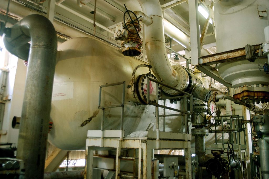
Measuring 20 metres long, the production separator was a horizontal tank with a diameter of four metres. It worked on the principle that the heaviest components in the tank would sink to the bottom while the lighter liquids and gas remained higher up.
This was a three-phase device with a lower phase of water, a middle one of crude oil and an upper gas phase. It was equipped internally with inlet deflectors, seven perforated guide plates and a demister for the gas outlet.
The test separator worked on the same principle, but was rather smaller. Its applications included testing the production rate from a single well so that the choke in the wellhead could be correctly adjusted.
Gas compression
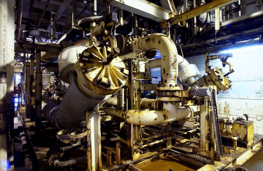
Compression was needed to increase the gas pressure before it entered the pipeline which ran to Ekofisk 2/4 R. The train comprised a gas cooler, suction scrubber and gas compressor.
Gas cooler. This reduced the temperature of gas emerging from the separator in order to prevent the compressor from running too hot. The gas circulated around a set of water-cooled tubes, lowering its temperature to 27°C.
Suction scrubber. Once the gas was cooled, some liquids had to be removed in this device. It comprised a vertical tank four metres tall and two metres in diameter.
Gas compressor. Driven by a gas turbine, this unit increased the pressure from 465 pounds per square inch gauge (psig) to 1 305psig while also raising the gas temperature from 27°C to 100°C.
Gas dehydration
Gas piped to Ekofisk 2/4 R had to be completely free of water to avoid ice or hydrate (hydrocarbon ice) plugs forming in the pipeline during transport through the cold seawater.
The gas was first cooled from 100°C to 27°C in two stages before being mixed with triethlyene glycol – a liquid which attracts water. After it had been dehydrated in this way, the gas was reheated to 65°C in a heat exchanger.
In all, the dehydration system comprised the gas/gas heat exchanger, the gas aftercooler and the glycol contactor.
Gas/gas heat exchanger. This had two functions – cooling down the incoming gas from 100°C to 60°C and heating up the outgoing gas from 27°C to 65°C. Two gas streams passed each other in the unit.
Gas aftercooler. This contained a number of water-cooled tubes which the gas circulated around to reduce the temperature from 60°C to 27°C.
Glycol contactor. This unit comprised a vertical tank 13 metres tall by two metres in diameter. The gas bubbled up through a number of vessel filled with glycol and ended up dehydrated at the top. Water-saturated glycol was circulated out and replaced by more dry chemical.
Fiscal metering
Oil and gas processed on the platform and exported to the Ekofisk Complex was metered in a metering station on 1/6 A. Data from these instruments were transmitted to a Daniel computer for processing before being transferred to the Ekofisk Complex via a telemetric link.
Corresponding meters were also provided for gas consumed on the platform and for the flare boom.
Gas metering. The gas meter comprised a tube containing pressure and temperature gauges, a densimeter and a flow orifice. When the gas passed through the orifice, its speed rose and its pressure fell. Knowing the density and composition of the gas meant the pressure drop could be used to measure the quantity exactly.
Oil metering. A turbine flow meter was used to meter oil. Small magnets located on the outer edge of the rotor transmitted signals to sensors in the rotor housing. The latter could then measure the speed at which the rotor turned, and thereby arrive at the exact amount of liquid flowing through the meter.
Calibration. Such turbine flow meters had to be calibrated regularly to ensure accurate measurements. Known as a meter prover, this system comprised a horseshoe-shaped test loop which contained a rubber ball.
During calibration, oil was conducted through the loop and pushed the ball ahead of it. Measuring how long the ball took to complete the circuit, given that the loop’s exact volume was known, made it possible to measure oil flow accurately. These data were then compared with the pulses from the turbine flow meter.
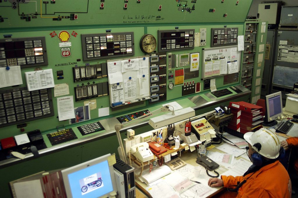
Control room
The control room was the platform’s heart, monitoring and controlling all important processes on board.
Utilities
Glycol regeneration Glycol coming from the gas dehydration facility had a pressure of 1 205psig and was saturated with water and gas. After its pressure had been reduced, the gas was removed in a degassing pot.
The glycol was then filtered and heated in the regenerator to evaporate the water, and passed through pumps to reach the same pressure as the dehydration unit before being returned to it.
Gas pipeline pigging. To remove slag and water from the gas pipeline, a sphere was launched into it at 1/6 A and followed the gas flow to Ekofisk 2/4 R where removal took place.
Oil pipeline pigging. The pig in the oil pipeline had a different shape to the unit used for the gas pipeline, but otherwise functioned in the same way.


Power supply
Electricity for the platform came from the generator room, where four generating sets were driven by Kongsberg gas turbines. Two of these turbines were later removed and replaced by a diesel engine. Electric switchboards were installed in the module above the generators. The working voltage was 480V.
Other utilities
Other utilities on the platform included fire extinguishing and rescue systems, instrument air, chemical injection and drinking water.
Also provided were diesel and lube oils, gas lift equipment, a workshop, helideck, accommodation module, flare boom, radio communications and so forth.
Production ceased in 1998, and the platform became unmanned in 1999 with remote monitoring from Ekofisk 2/4 K. After the processing plant had been cleaned and the wells were plugged and secured, the platform was removed during 2013.